Create project
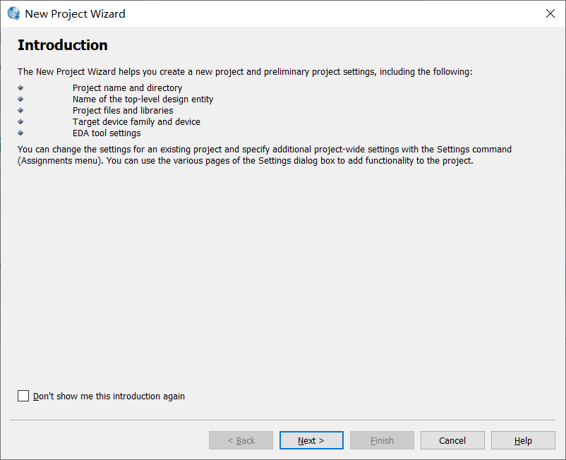
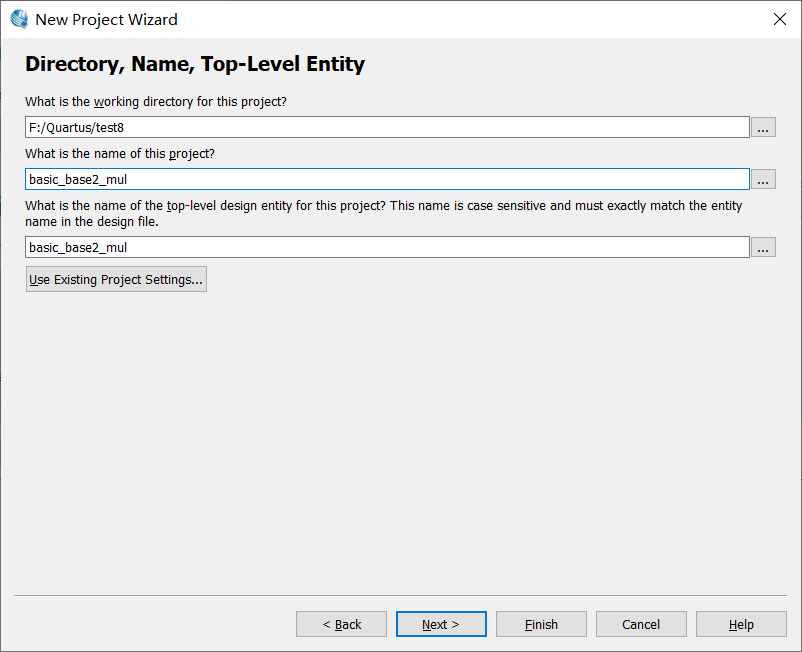
Find a place to create a new folder, set the path of this project to that folder, and the project name can be taken by yourself (in order to avoid inconsistency later, it is recommended to take the same as me)
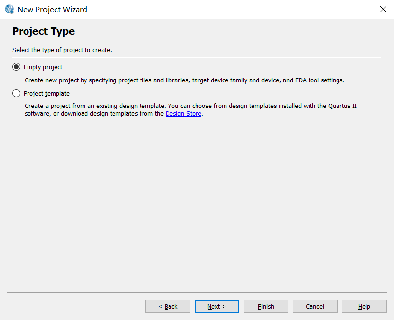
Create from empty project
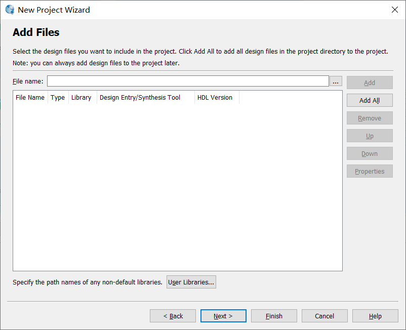
No files need to be added
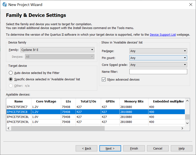
Select the development board, I choose this, and then next
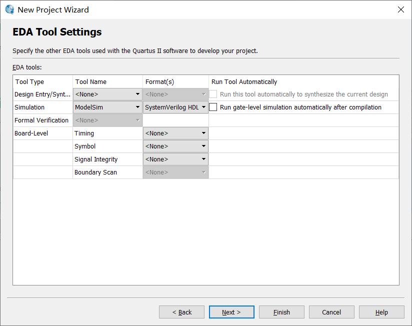
Select the simulation mode as modelsim, and then select SystemVerilog, regardless of others, and then next
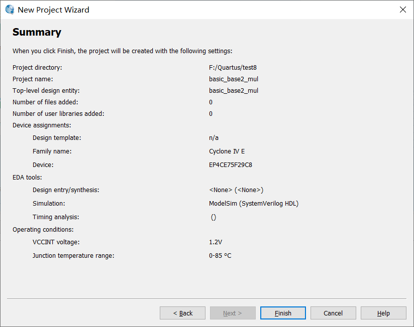
See some information about the project, finish and wait for the creation
After the project is created, do some preparatory work
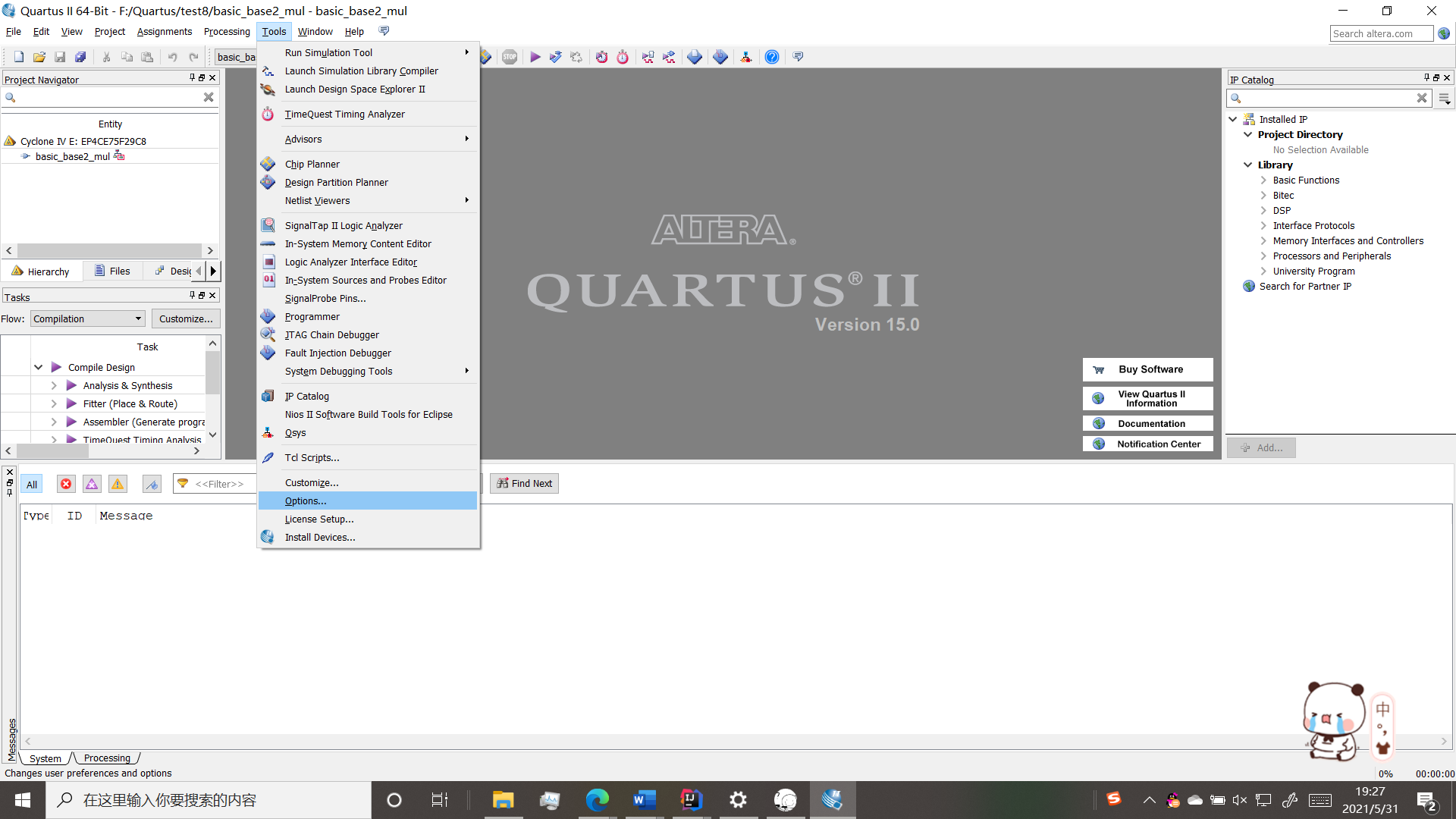
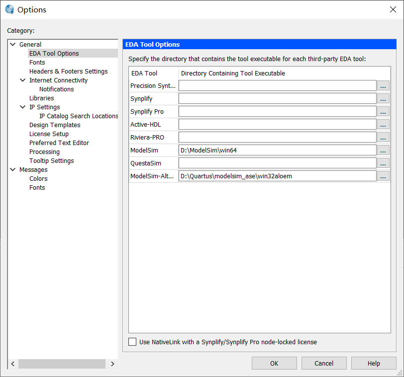
Set the path of modelsim to facilitate joint simulation
Tools options EDA tools options, set the path of Modelsim to win64 under the path of locally installed Modelsim, ok to exit
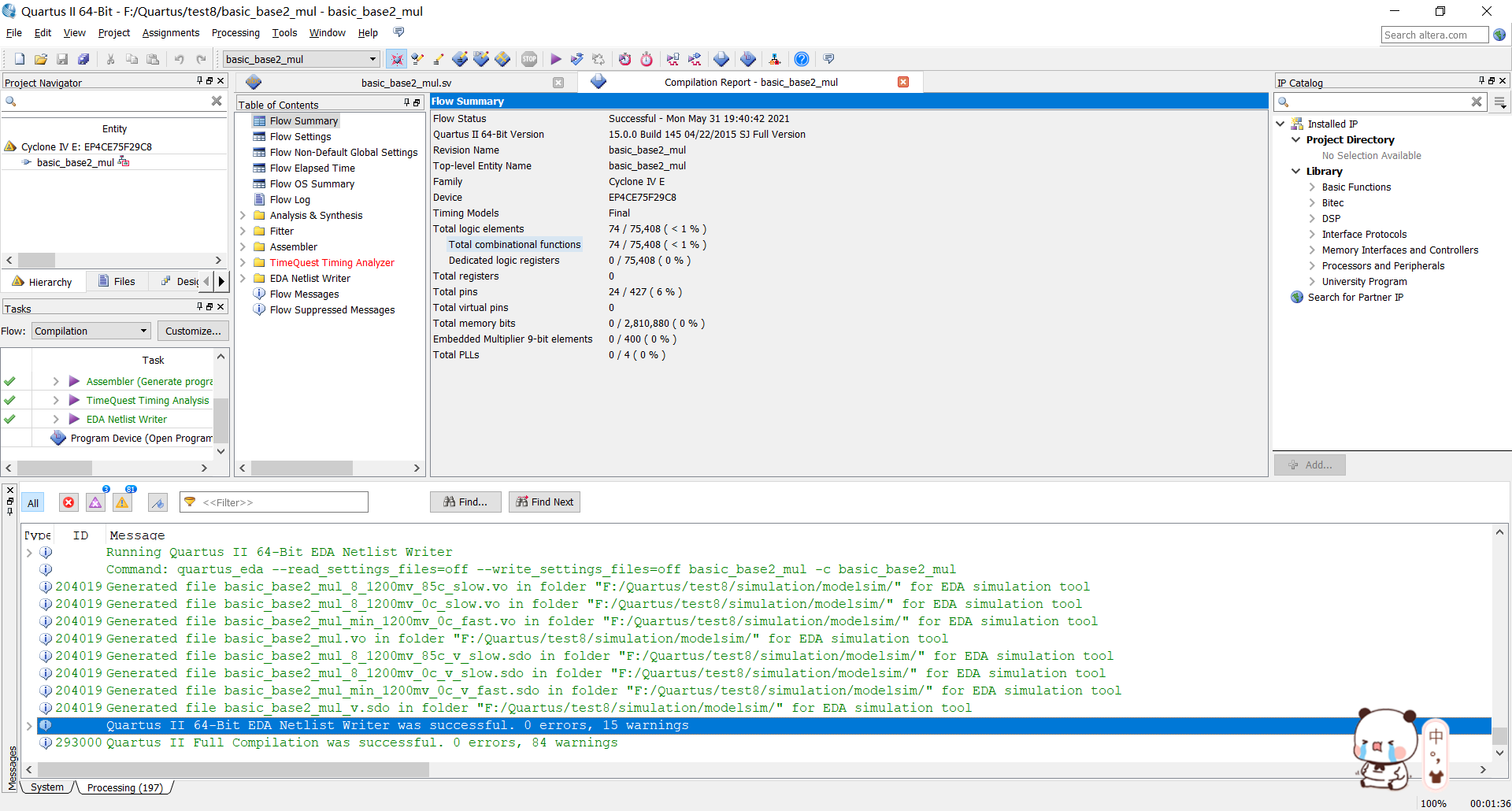
When you're ready, you can start writing code
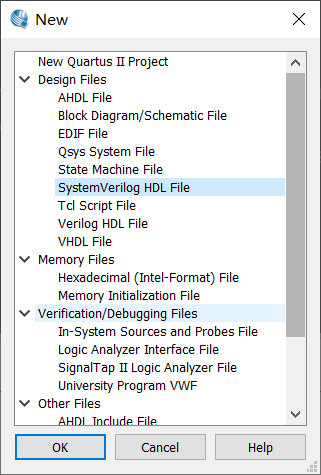
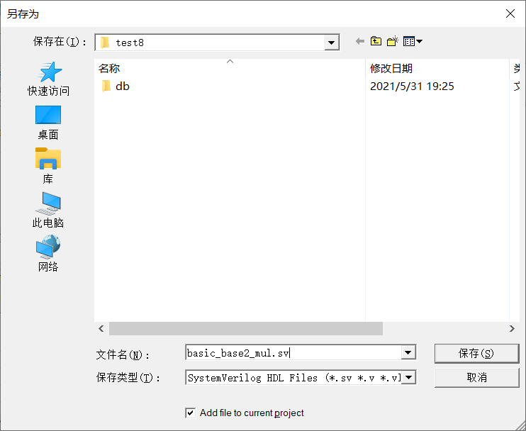
Create a new systemverilog, dip the multiplier code into it and save it. Remember that the module name and file name should be the same. Remember to run it after saving
module basic_base2_mul(x_in, y_in, p_out);
	parameter 	N = 8,
				M = 4;
	input logic [N-1:0] x_in;
	input logic [M-1:0] y_in;
	output logic [N+M-1:0] p_out;

	integer i;
	reg [M:0] wires[N:0];
	initial
	   begin
	       for (i=0;i<=N;i=i+1) begin
	          wires[i]=0;
	          end
	   end


	always @(x_in or y_in)begin
		for(i=0; i<=N-1; i=i+1)begin
			wires[i+1] = mult_by_1(x_in[i], wires[i][M:1], y_in);
			p_out[i] = wires[i+1][0];
		end
		p_out[N+M-1:N] = wires[N][M:1];
	end

	function [M:0] mult_by_1;
		input			xi;
		input  [M-1:0] 	A, B;

		if(xi)	mult_by_1 = A + B;
		else	mult_by_1 = A;
	endfunction
endmodule
Generate testbench to facilitate the generation of excitation signal files, and use testbench to automatically generate templates
Processing-star-star testbench writer
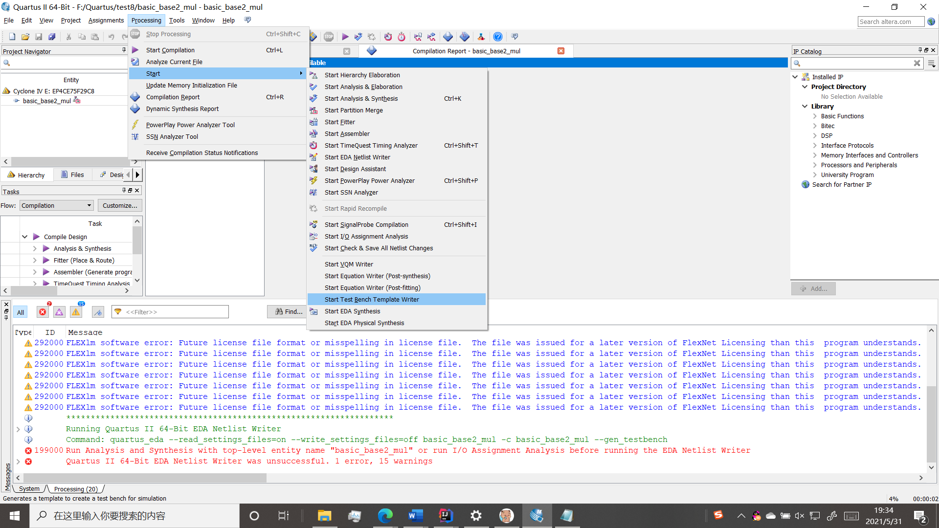
Try this first. If you report this error, you can
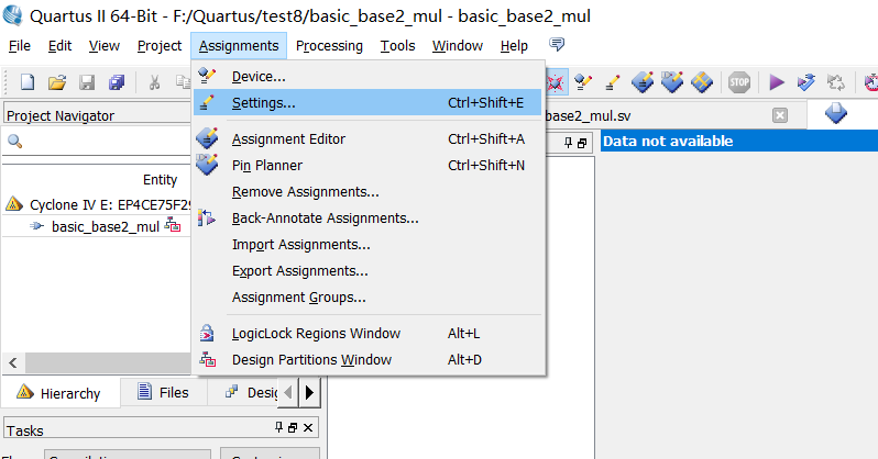
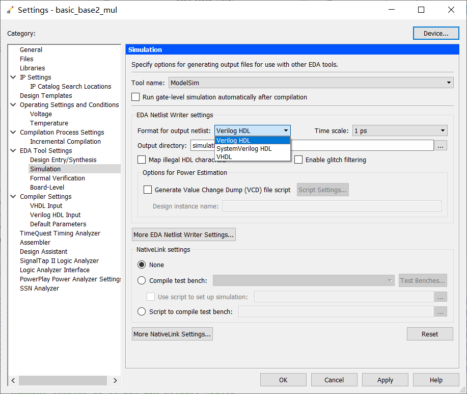
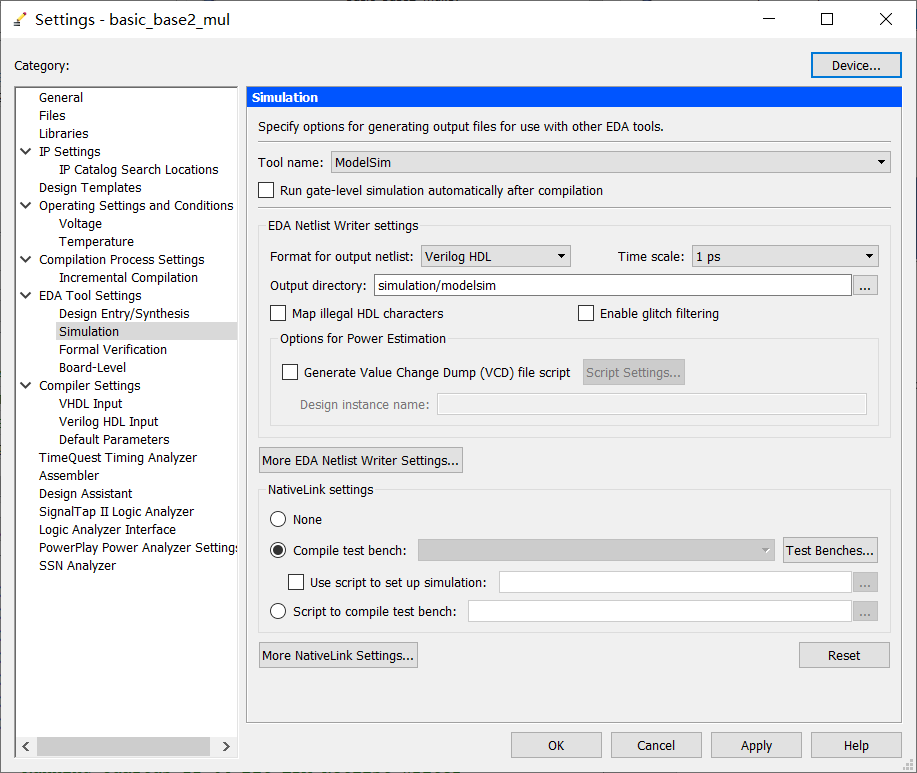
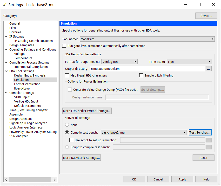
In the setting of assignment, operate according to the following picture and change it to verilog. Remember to apply
Then go to star again and follow the above steps to generate the incentive file
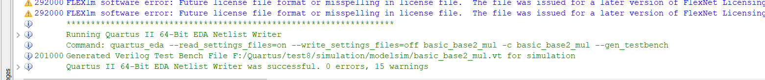
Then apply the incentive document to the project
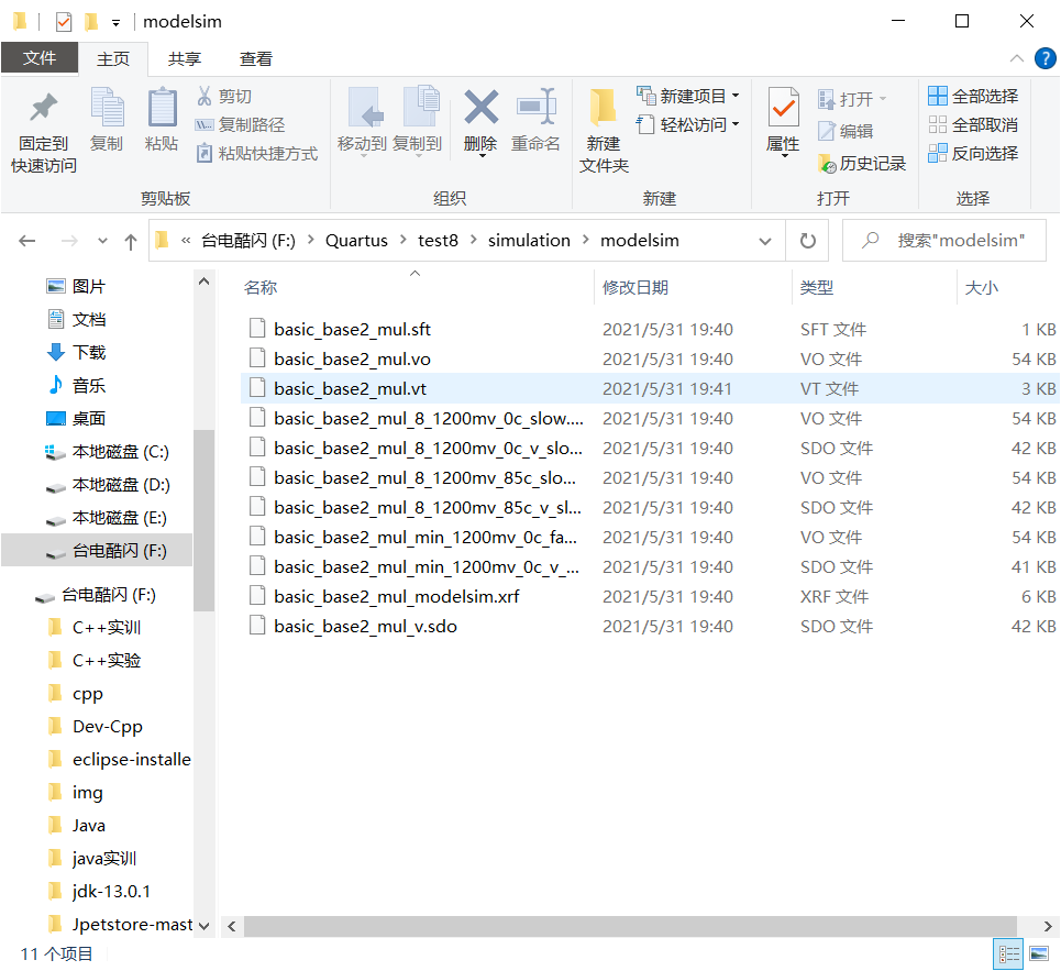
In the folder of your own project, you will find that this file is generated automatically (if some versions of QuartusII are not generated automatically, you will create a vt file and put it in this directory. Paste the following code in it)
Open the notepad and modify the signal of the incentive file inside
There is a little change from the back of timescale. My code is here (I cut the picture when the teacher opens this file in class. The first line below the teacher uses ns, but I didn't change it. In fact, I just need to add the content in initial). After the change, save it and set the path of this file in quartus
`timescale 1 ps/ 1 ps

module basic_base2_mul_vlg_tst();

// constants

// general purpose registers

reg eachvec;

// test vector input registers

reg [7:0] x_in;

reg [3:0] y_in;

// wires

wire [11:0]  p_out;


// assign statements (if any)

basic_base2_mul i1 (

// port map - connection between master ports and signals/registers

       .p_out(p_out),

       .x_in(x_in),

       .y_in(y_in)

);

initial

begin

// code that executes only once

// insert code here --> begin

x_in = 8'd0;  y_in = 4'd2;

#30

x_in = 8'b00000100; y_in = 4'b0100;

// --> end

$display("Running testbench");

end

always

// optional sensitivity list

// @(event1 or event2 or .... eventn)

begin

// code executes for every event on sensitivity list

// insert code here --> begin


@eachvec;

// --> end

end

endmodule
Go to assignment setting simulation again, and select compile testbench
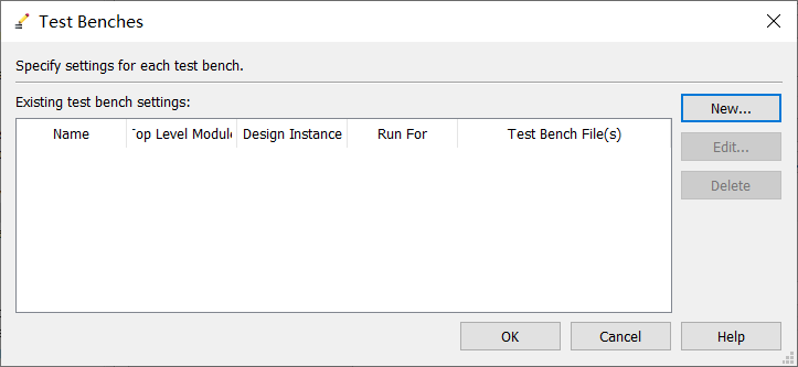
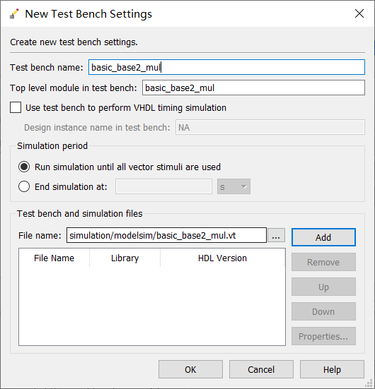
Click below to browse the file, go into the directory, find the file, add, ok and apply all the way back
noodles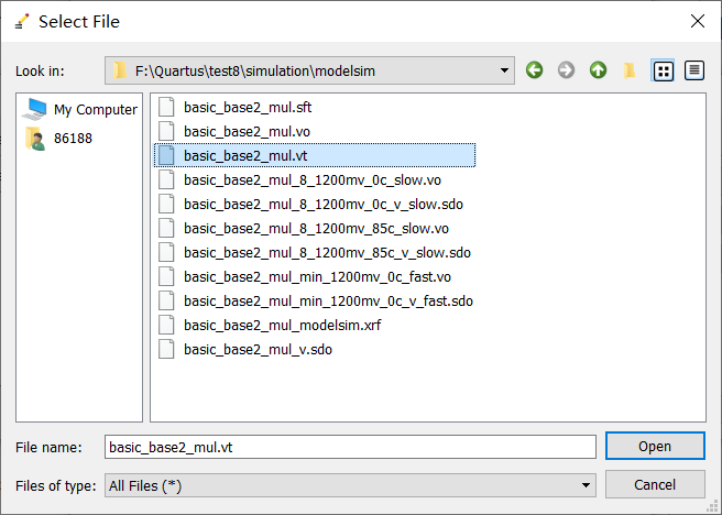
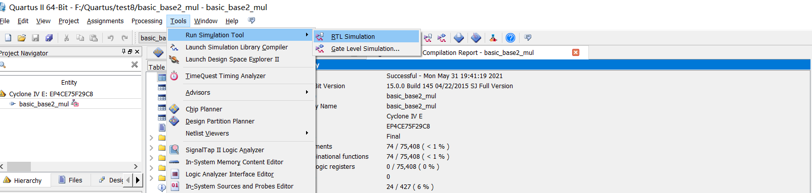
Skip to RTL and go to modelsim
Open it here until the compilation is completed
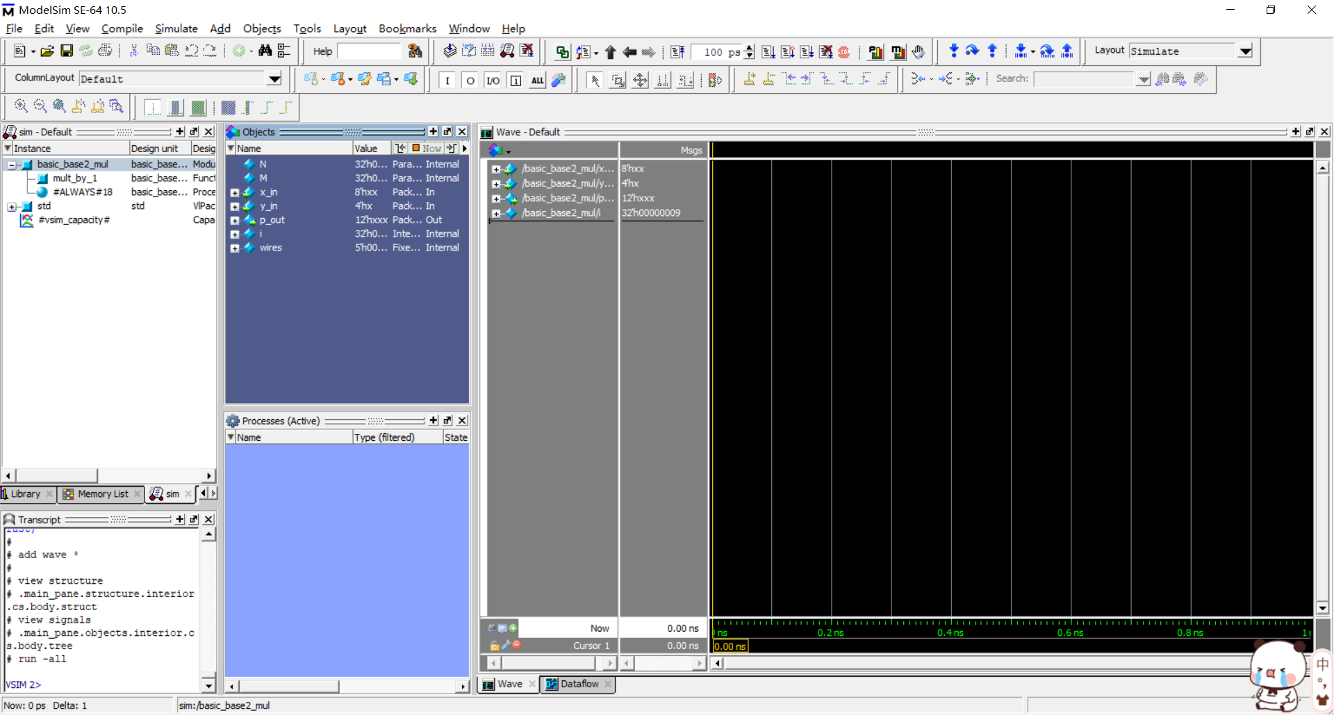
Click run here to see the cable coming out
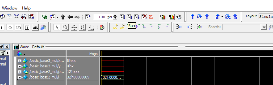 However, there is no data at this time, because 8 'hxx, followed by xx represents data
8 means 8 binary bits, that is, the following number is 8 bits, and h represents this number in hexadecimal. xx actually tells you that you can write two digits in the following, because two hexadecimal bits are equivalent to eight binary bits (I think so)
Right click the location and force set the data
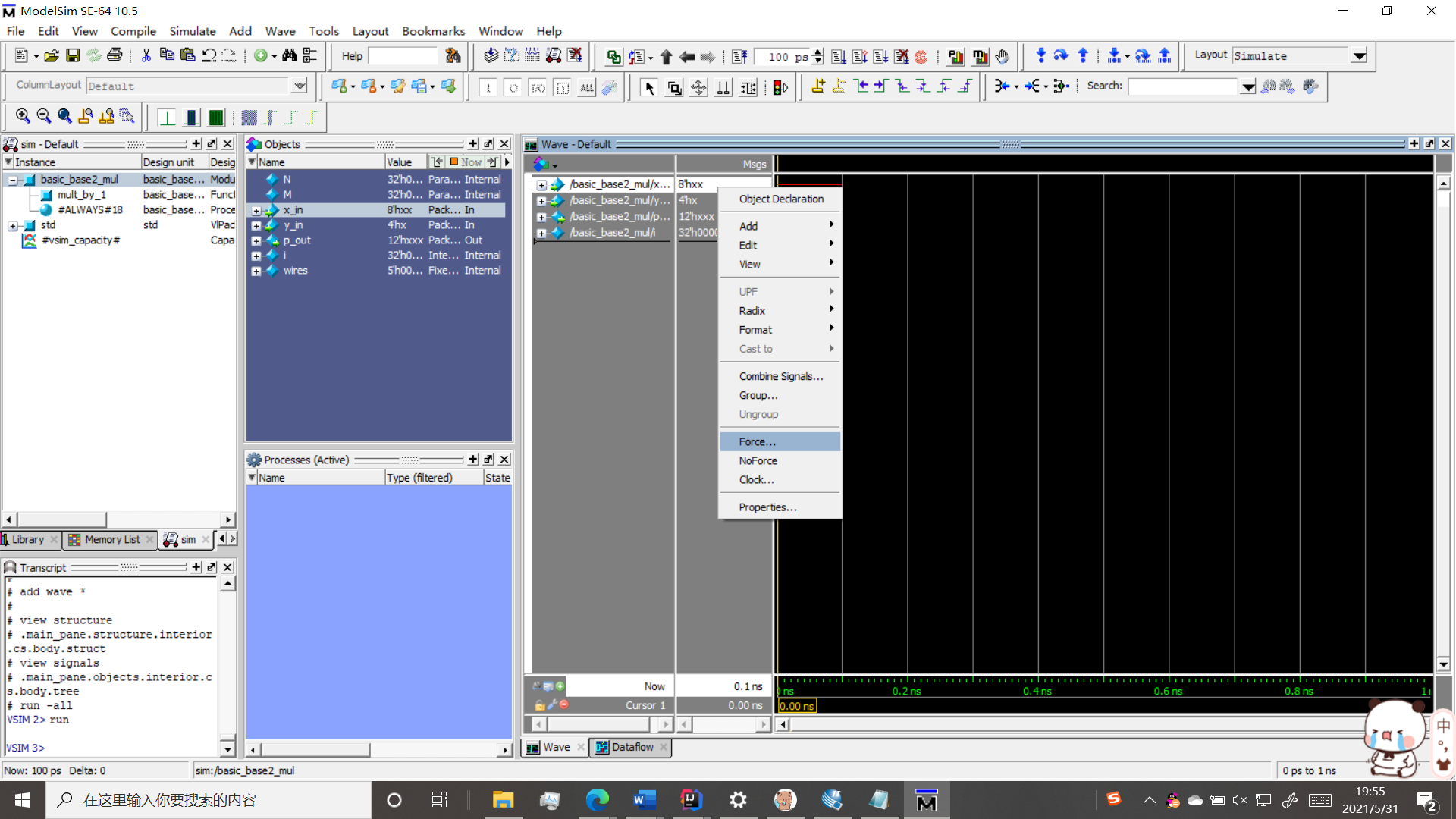
Set the first and second, that is, x and y
This is a multiplier, so you can get the answer
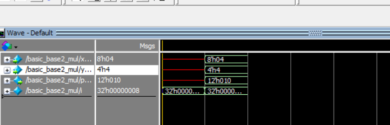
Change it again and run again, and all kinds of results will come out
Hexadecimal multiplication full 16 into 1
4*4 = 16
Therefore, enter 1 and 0 to get the result 10, which is in the third line