Problem background
Today, I encountered a problem when writing uart serial port code and simulating. Two signals send in uart module_ EN and tx_state. The original expectation was send_en a clock high level appears, TX_ The high state indicates that the serial port is transmitting data. The code is as follows:
//tx_state signal
    always@(posedge clk or negedge rst_n)begin
        if(!rst_n)
            tx_state <= 1'b0;
        else if(send_en)
            tx_state <= 1'b1;
        else if(baud_clk_cnt == 4'd11)
            tx_state <= 1'b0;
        else
            tx_state <= tx_state;
    end
But there is a problem in the simulation: send_ The en signal appears before the high level of a clock, TX_ The state signal has been pulled up.
The simulation is shown in the figure below:
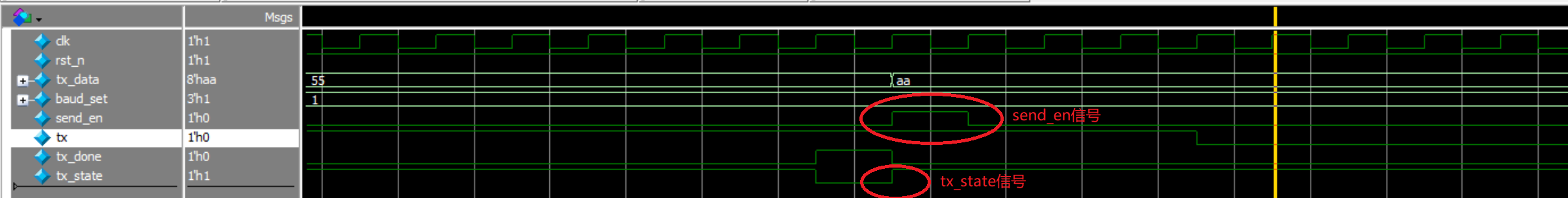
As can be seen from the figure, send_ The en signal is not high, but TX_ The state signal has changed.
reason
This is because there is no special distinction between blocking assignment and non blocking assignment in the simulation code.
The simulation code is as follows:
initial clk = 1;
    always #(`clock_period/2) clk = ~clk;

    initial begin
        rst_n = 0;
        send_en = 0;
        tx_data = 8'h55;
        baud_set = 3'b001;
        #(`clock_period*50);
        rst_n = 1;
        #(`clock_period*500);
        send_en = 1;
        #(`clock_period);
        send_en = 0;
        @(posedge tx_done);
        #(`clock_period);
        send_en = 1;
        tx_data = 8'haa;
        #`clock_period;
        send_en = 0;
        #(`clock_period*500);
        @(posedge tx_done);
        #(`clock_period*50000);
        $stop;
    end
It can be seen from the above code that all simulation statements use non blocking assignment, and all signals are generated by non blocking assignment. At this time, clk sampling will extract the signal value after the rising edge if it encounters the rising edge of the signal. The previous problem is that in the figure, it can be seen that the signal extracted by the clk signal on the rising edge is send_ The value after the rising edge of the en signal is the high level, and TX can be driven at this time_ The state signal becomes high, so send appears_ The change of en did not cause TX_ The state signal changes.
resolvent
Here you just need to send_ The assignment of en signal can be changed from non blocking assignment to blocking assignment. At the same time, we also turn other signals other than the clock signal into blocking assignment.
initial clk = 1;
    always #(`clock_period/2) clk = ~clk;

    initial begin
        rst_n <= 0;
        send_en <= 0;
        tx_data <= 8'h55;
        baud_set <= 3'b001;
        #(`clock_period*50);
        rst_n <= 1;
        #(`clock_period*500);
        send_en <= 1;
        #(`clock_period);
        send_en <= 0;
        @(posedge tx_done);
        #(`clock_period);
        send_en <= 1;
        tx_data <= 8'haa;
        #`clock_period;
        send_en <= 0;
        #(`clock_period*500);
        @(posedge tx_done);
        #(`clock_period*50000);
        $stop;
    end
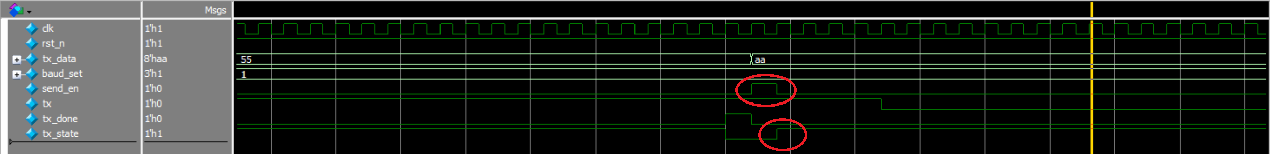
The simulation results are shown in the figure below
reflection
This problem makes us notice that blocking assignment and non blocking assignment also need to be considered in the simulation, otherwise the code may be correct but inconsistent with the simulation.
Here I also specially write a counter to determine rst_n signal uses the difference between blocking assignment and non blocking assignment in simulation.
cnt_test.v
module cnt_test(
    clk,
    rst_n,
    cnt
);
    input clk;
    input rst_n;
    output reg [7:0]cnt;

    always@(posedge clk or negedge rst_n)begin
        if(~rst_n)
            cnt <= 8'd0;
        else if(cnt == 8'd99)
                cnt <= 8'd0;
        else
            cnt <= cnt + 1'b1;
    end
endmodule
Simulation code
cnt_test_tb.v
`timescale 1ns/1ns
`define clock_period 20
module test_tb;

    reg clk;
    reg rst_n;
    wire [7:0]cnt;

    test u_test(
        .clk    ( clk    ),
        .rst_n  ( rst_n  ),
        .cnt    ( cnt    )
    );

    initial begin
        clk = 1'b1;
        forever begin
            #10 clk = ~clk;
        end
    end

    initial begin
        rst_n <= 1'b0;
        #(`clock_period*10);
        rst_n <= 1'b1;
        #(`clock_period*500);
        $stop;
    end

endmodule
Interested friends can take a look at changing the blocking assignment in the simulation code to non blocking assignment, where RST_ The influence of N on the counter cnt.