-
summary
This section mainly exercises the basic grammar of verilog.
-
Schematic diagram + code + simulation screenshot
- Alwaysblock1
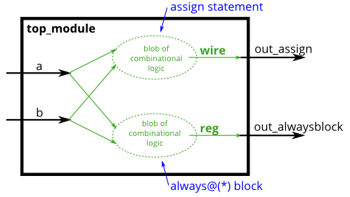
There are two types of composite awlays modules that can be integrated:
- always @(*); The variable processed inside is reg, and the overall function is equivalent to the assign statement. The assign statement cannot be used inside; You can use if then, case and other syntax. As long as the input changes, the output changes:
- assign out1 = a & b | c ^ d; // Out1 to the left of the equal sign must be a wire type variable,
- always @(*) out2 = a & b | c ^ d; // Out2 to the left of the equal sign must be a variable of type reg.
- The functions of the above two codes are the same.
- always @(posedge clk)
// synthesis verilog_input_version verilog_2001
module top_module(
    input a,
    input b,
    output wire out_assign,
    output reg out_alwaysblock
);

    assign out_assign = a & b;

    always @(*)
        out_alwaysblock = a & b;
endmodule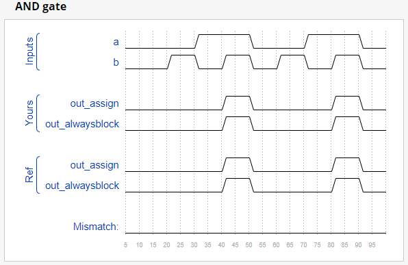
- Alwaysblock2
Let's continue to practice using always:
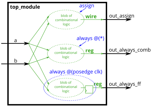
- Combinational: always @(*):
- Equivalent to Assign to realize combined circuit
- Only blocking assignments (a=b) can be used.
- blocking
- Clocked: always @(posedge clk) :
- It can also achieve the combinational circuit function of always @ (*), but it can also realize the trigger (register) function,
- This means that only the edge of the clock can output values.
- Only non blocking assignments (a < = b) can be used.
- non-blocking.
- assign:
- Continuous replication,
- Key values cannot appear in the always block
// synthesis verilog_input_version verilog_2001
module top_module(
    input clk,
    input a,
    input b,
    output wire out_assign,
    output reg out_always_comb,
    output reg out_always_ff   );

    assign out_assign = a ^ b;

    always @(*)
        out_always_comb = a ^ b;

    always @(posedge clk)
        out_always_ff <= a ^ b;
endmodule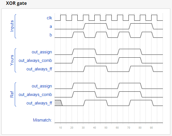
- Always if
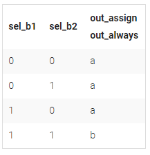
The if statement is used in the always block, which is similar to the c language. Try to take else scenarios into account. If else scenario is not considered, it is necessary to initialize the output signal.
// synthesis verilog_input_version verilog_2001
module top_module(
    input a,
    input b,
    input sel_b1,
    input sel_b2,
    output wire out_assign,
    output reg out_always   );

    assign out_assign = (sel_b1 == 1 && sel_b2 == 1) ? b : a;

    always @(*) begin
            if(sel_b1 == 1 && sel_b2 == 1) begin
    			out_always = b;
            end
        	else begin
               out_always = a;
            end
    end
endmodule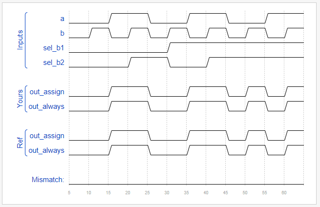
- Always if2
Be sure to take else scenarios into account. If else scenario is not considered, it is necessary to initialize the output signal. For this problem, the initial practice has gone far, and the state machine is actually used. In fact, the original intention of this topic is to describe the else scene.

Method 1:
// synthesis verilog_input_version verilog_2001
module top_module (
    input      cpu_overheated,
    output reg shut_off_computer,
    input      arrived,
    input      gas_tank_empty,
    output reg keep_driving  ); //

    reg shut_off_state,shut_off_state_ns;
	reg drive_state, drive_ns;

    always @(*) begin
        shut_off_state = shut_off_state_ns;
    end

    always @(*) begin
    	if (cpu_overheated)
       		shut_off_state_ns = 1;
  		else
            shut_off_state_ns = 0;
    end

    always @(*) begin
    	if (shut_off_state)
       		shut_off_computer = 1;
  		else
            shut_off_computer = 0;
    end


    always @(*) begin
       drive_state = drive_ns;
    end

    always @(*) begin
        if(~arrived && ~gas_tank_empty)
            drive_ns = 1;
        else
            drive_ns = 0;
    end

    always @(*) begin
        if(drive_state)
            keep_driving = 1;
        else
            keep_driving = 0;
    end

endmodule
Method 2:
// synthesis verilog_input_version verilog_2001
module top_module (
    input      cpu_overheated,
    output reg shut_off_computer,
    input      arrived,
    input      gas_tank_empty,
    output reg keep_driving  ); //

    always @(*) begin
        if (cpu_overheated)
           shut_off_computer = 1;
        else
           shut_off_computer = 0;
    end

    always @(*) begin
        if (~arrived)
           keep_driving = ~gas_tank_empty;
        else
           keep_driving = 0;
    end

endmodule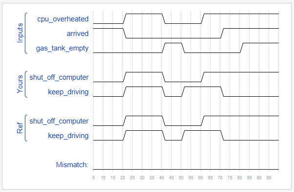
- Always case
Different from C syntax, there is no Switch keyword. Like if, the else scenario must be considered. There must be a default scenario. Unlike the C language, each case project is executed only once, so the Break keyword is not required.
// synthesis verilog_input_version verilog_2001
module top_module (
    input [2:0] sel,
    input [3:0] data0,
    input [3:0] data1,
    input [3:0] data2,
    input [3:0] data3,
    input [3:0] data4,
    input [3:0] data5,
    output reg [3:0] out   );//

    always@(*) begin  // This is a combinational circuit
        case(sel)
            0: out = data0;
            1: out = data1;
            2: out = data2;
            3: out = data3;
            4: out = data4;
            5: out = data5;
            default: out = 0;
        endcase
    end

endmodule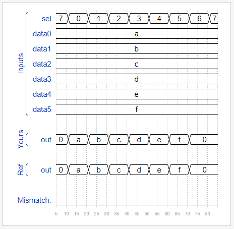
- Always case2
About this question, I mainly practice the other two variants of Case: casez and casex
// synthesis verilog_input_version verilog_2001
module top_module (
    input [3:0] in,
    output reg [1:0] pos  );

    always @(*) begin
        casex(in)
            4'bxxx1: pos = 0;
            4'bxx10: pos = 1;
            4'bx100: pos = 2;
            4'b1000: pos = 3;
            default: pos = 0;
        endcase
    end
endmodule- Always casez
// synthesis verilog_input_version verilog_2001
module top_module (
    input [7:0] in,
    output reg [2:0] pos  );

    always @(*) begin
        casez(in)
            8'bzzzzzzz1: pos = 3'd0;
            8'bzzzzzz10: pos = 3'd1;
            8'bzzzzz100: pos = 3'd2;
            8'bzzzz1000: pos = 3'd3;
            8'bzzz10000: pos = 3'd4;
			8'bzz100000: pos = 3'd5;
			8'bz1000000: pos = 3'd6;
            8'b10000000: pos = 3'd7;
            default: pos = 3'd0;
        endcase
    end
endmodule- Always nolatches
This problem is mainly to prevent the latch problem. When default cannot cover all possible, the output value should be initialized in advance.
// synthesis verilog_input_version verilog_2001
module top_module (
    input [15:0] scancode,
    output reg left,
    output reg down,
    output reg right,
    output reg up  );

    always @(*) begin
    	up = 1'b0;
        down = 1'b0;
        left = 1'b0;
        right = 1'b0;
        case(scancode)
            16'he06b: left = 1'b1;
            16'he072: down = 1'b1;
            16'he074: right = 1'b1;
            16'he075: up = 1'b1;
        endcase
    end

endmodule 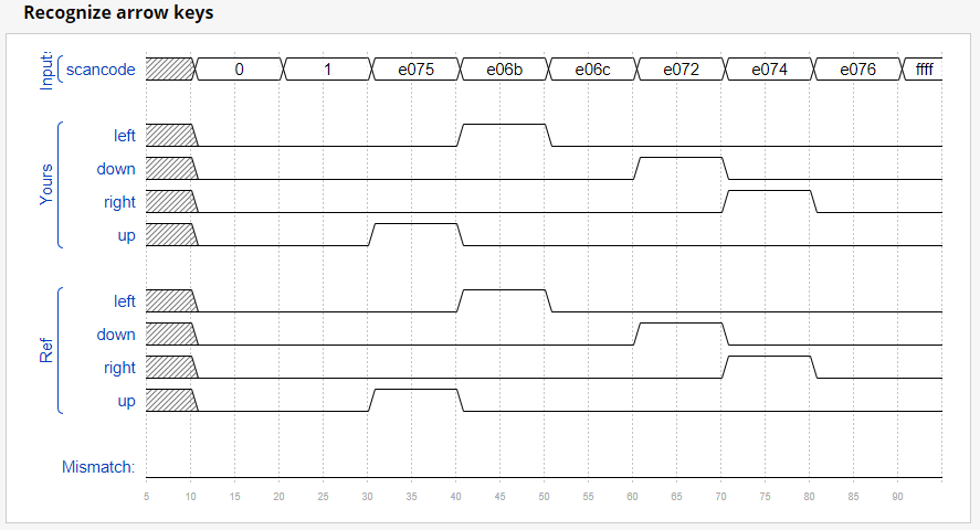
- Conditional
This topic mainly exercises three conditional operations: (condition) ? if_true : if_false)
module top_module (
    input [7:0] a, b, c, d,
    output [7:0] min);//

    // assign intermediate_result1 = compare? true: false;
    assign min = (a<b && a<c && a<d) ? a:((b<c && b<d) ? b : (c<d)?c:d);

endmodule- Reduction &Gates100
Reduce the syntax for continuous bit logic operations:
& a[3:0]     // AND: a[3]&a[2]&a[1]&a[0]. Equivalent to (a[3:0] == 4'hf)
| b[3:0]     // OR:  b[3]|b[2]|b[1]|b[0]. Equivalent to (b[3:0] != 4'h0)
^ c[2:0]     // XOR: c[2]^c[1]^c[0]
//Reduction
module top_module (
    input [7:0] in,
    output parity);

    assign parity = ^in[7:0];
endmodule
//Gates100
module top_module(
input [99:0] in,
output out_and,
output out_or,
output out_xor
);
assign out_and = & in[99:0];
assign out_or = | in[99:0];
assign out_xor = ^ in[99:0];
endmodule- Vector100r
module top_module(
    input [99:0] in,
    output [99:0] out
);

    int i;
    always @(*) begin
        for(i=0; i<=99;i++)begin
            out[i] = in[99-i];
        end
    end
endmodule- Popcount255
//Method 1
module top_module(
    input [254:0] in,
    output [7:0] out );

    integer i;

    always @(*) begin
        out = 0;
        for(i=0; i <= 254; i=i+1)
            if(((in>>i) & 1'b1) == 1'b1)
            out = out + 1;
    end

endmodule
//Method 2
module top_module(
input [254:0] in,
output [7:0] out );
integer i;
always @(*) begin
out = 0;
for(i=0; i <= 254; i=i+1)
out = out + in[i];
end
endmodule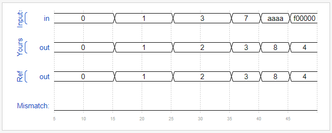
- adder100i
Create a 100bit adder directly instead of instantiating it.
module top_module(
    input [99:0] a, b,
    input cin,
    output [99:0] cout,
    output [99:0] sum );

    integer i;
    always @(*) begin
        {cout[0],sum[0]} = a[0]+b[0]+ cin;
       for(i=1;i<=99;i=i+1) begin
           {cout[i],sum[i]} = a[i]+b[i]+ cout[i-1];
           end
    end

endmodule- Bcdadd100
This question is different from the previous one. The main exercise of this question is: generate endgenerate
module top_module(
    input [399:0] a, b,
    input cin,
    output cout,
    output [399:0] sum );


    wire[99:0] cout_temp;

    generate
		genvar i;
        for(i=0; i<=99; i=i+1)begin:add_400
            if(i == 0)begin
                bcd_fadd  inst(
                    .a(a[3:0]),
                    .b(b[3:0]),
                    .cin(cin),
                    .cout(cout_temp[0]),
                    .sum(sum[3:0])
                );
            end
            else begin
                 bcd_fadd  insts(
      				.a(a[i*4+3 : i*4]),
                    .b(b[i*4+3 : i*4]),
                    .cin(cout_temp[i-1]),
                    .cout(cout_temp[i]),
                    .sum(sum[i*4+3 : i*4])
            );
            end
        end
		assign cout=cout_temp[99];
    endgenerate
endmodule-
summary
Up to now, all the grammar knowledge of Verilog has been basically practiced. The key is to do the topic with the idea of circuit, not like C language.