tinyriscv, the core cpu part of SoC project, is designed with the classic three-stage pipeline structure, which is well-known: value - > decoding - > execution three-stage pipeline.
The execution module was annotated in the previous blog post. Now let's introduce the interrupt module:
catalogue
1. Interrupt structure diagram
2. csr_reg control and status register
2.1 overview of interrupts and exceptions
4. ctrl.v module (jump and pipeline pause)
4.2 function overview (refer to the original blog)
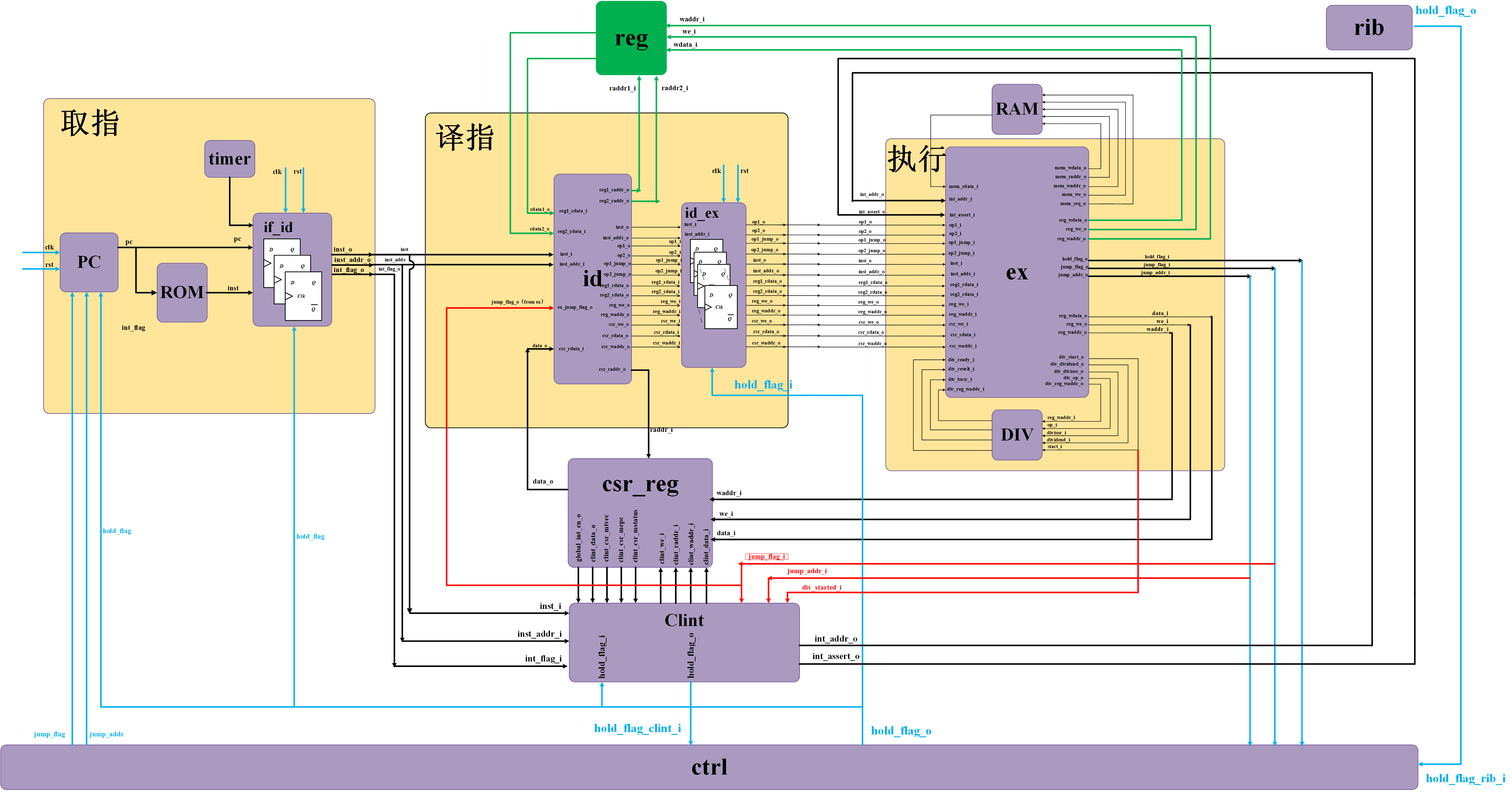
1. Interrupt structure diagram
Interrupt part of RISC-V kernel: involving {csr_reg.v,clint.v,ctrl.v and other modules. Since the interrupt module is closely related to the three-stage pipeline, we place the overall structure diagram of the kernel here to annotate the interrupt control part:
2. csr_reg control and status register
2.1 overview of interrupts and exceptions
- Interrupt mechanism, that is, the processor core is suddenly interrupted by other requests in the process of sequential execution of program instruction flow, and stops executing the current program, turns to deal with other things, waits for it to deal with other things, and then returns to the point of previous program interrupt to continue executing the previous program instruction flow.
- Exception mechanism, that is, when the processor core suddenly encounters an exception in the process of sequential execution of program instruction flow, it stops executing the current program and handles the exception instead. Synchronization exception: it is an instruction exception, which can locate the instruction with. Asynchronous exception: cannot locate a specific instruction.
- The difference between interrupt and exception: exceptions are generally caused by events inside the processor or during program execution.
- In a broad sense: interrupts and exceptions are called exceptions.
RISC-V architecture exception handling mechanism:
- At present, RISCV architecture documents are mainly divided into "instruction set documents" and "privileged architecture documents". The exception handling mechanism of RISC-V architecture is defined in the "privileged architecture document". RISC-V architecture can have not only machine mode, but also user mode, supervisor mode and other working modes. Exceptions can be generated in different modes, and some modes can also respond to interrupts. RISC-V architecture requires that the machine mode is a required mode, and other modes are optional rather than mandatory.
- The difference between interrupt, jump and pause: interrupt and jump are the reasons for triggering pause. Interrupt operation is to improve the execution efficiency of the program. In interrupt or for loop, there will be jump operation.
• exit interrupt: use the interrupt return command MRET, which is necessary in machine mode.
• interrupt type:
External interrupt: the interrupt that occurs in the peripheral, which occurs outside the processing core.
Timer interrupt (one of external interrupts): controlled by mtie field in mie register.
Software interrupt: an interrupt triggered by the software itself (C language and other software languages).
Debug interrupt: the interrupt during Dubug.
• interrupt mask: control different types of interrupt enable and mask (external interrupt, timer interrupt, software interrupt) through MIE register.
2.2 csr_reg.v basic knowledge
CSR register module (csr_reg.v) and general register module reg The read and write operations of V are similar and will not be repeated here.
csr_reg.v, the main registers used and their meanings are as follows:
- mtvec(Machine Trap Vector): save the address that the processor needs to jump when an exception occurs (used to set the entry of interrupts and exceptions). Interrupt and exception need to jump to different base addresses.
- mcause(Machine Exception Cause): when an interrupt or exception is generated, the type of interrupt or exception currently generated will be recorded in the mcause register.
- mepc(Machine Exception PC): save the address of the exception instruction (the address returned by the interrupt). When an interrupt or exception occurs under RISCV, the hardware automatically saves the return address in the mepc register. When it returns in the interrupt processing, the hardware automatically assigns the address in the mepc to the PC for operation. (pc+4)
- mstatus(Machine Status): global interrupt enable and other status information. As the name suggests, this register is used to control some current state information of the cpu core, such as global interrupt enable. The specific explanation is as follows (interrupt cannot be nested by default):
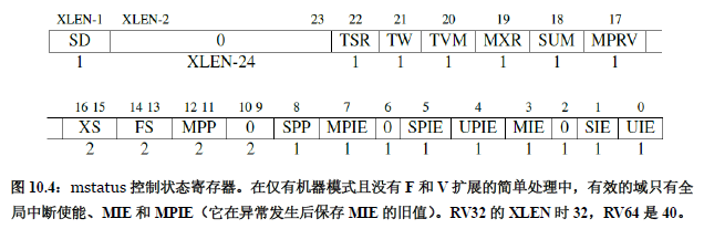
mstatus [3] mie: interrupt global enable, 1 = enable global interrupt, 0 = close global interrupt. After an interrupt occurs, 1 becomes 0.
mstatus [7] mpie: stores the value of mie before the interrupt occurs.
mie(Machine Interrupt Enable): indicates the interrupts that the processor can handle and ignore at present. The three interrupt types have corresponding interrupt enable bit settings in m mode and s mode, which is realized through mie register.
Mscract (machine srcatch register): the mscract register is used to temporarily save some data for programs in machine mode. Mscratch register can provide a fast save and restore mechanism. For example, after entering the exception handler in machine mode, temporarily store the value of a general register of the application in the mscratch register, and then read the value in the mscratch register back to the general register before exiting the exception handler.
Clock cycle counter (64bit): mcycle, mcycleh
- mcycle: the lower 32 bits of the count value
- mcycleh: upper 32 bits of count value
2.3 csr_reg.v annotation
The input and output interfaces are as follows:
input wire clk,
input wire rst,
// form ex
input wire we_i,                        // ex module write register flag
input wire[`MemAddrBus] waddr_i,        // (from id!!!) ex module write register address 32 bits
input wire[`RegBus] data_i,             // ex module writes 32 bits of register data
// form id
input wire[`MemAddrBus] raddr_i,        // ex module read register address 32 bits
// to id
output reg[`RegBus] data_o              // id module reads register data
// from clint
input wire clint_we_i,                  // clint module write register flag
input wire[`MemAddrBus] clint_raddr_i,  // Register read address module clint
input wire[`MemAddrBus] clint_waddr_i,  // clint module write register address
input wire[`RegBus] clint_data_i,       // clint module writes register data
// to clint
output wire global_int_en_o,            // Global interrupt enable flag
output reg[`RegBus] clint_data_o,       // clint module reads register data (not used)
output wire[`RegBus] clint_csr_mtvec,   // mtvec saves the address that the processor needs to jump to when an exception occurs
output wire[`RegBus] clint_csr_mepc,    // mepc saves the address of the exception instruction
output wire[`RegBus] clint_csr_mstatus, // mstatus global interrupt enable and other status information
csr_reg.v main functions:
Several CSR registers and a 64 bit counter are defined in the program (the counter counts all the time after the reset is cancelled, and counts the total number of cycles since the CPU is reset. (the core clock may be dynamically adjusted)).
Write register: according to the last 12 bits of the write register address, send the data in the ex or clint module to the control and status register (CSR register);
Read register (combinational logic): the address of the read register comes from the decoding id module, and sends the data read from the register to the decoding id module (according to the last 12 bits of the read register address). The address of the read register comes from the interrupt clint module, and sends the data read from the register to the clint module (according to the last 12 bits of the read register address).
3. clint.v module annotation
3.1 interface definition
input wire clk,
input wire rst,

// from core
input wire[`INT_BUS] int_flag_i,         // Interrupt input signal (timer interrupt input)

// from id
input wire[`InstBus] inst_i,             // Instruction content
input wire[`InstAddrBus] inst_addr_i,    // Instruction address

// from ex
input wire jump_flag_i,
input wire[`InstAddrBus] jump_addr_i,
input wire div_started_i, //Division start flag (1 when division is performed, and the program cannot respond to synchronization interrupt)

// from ctrl
input wire[`Hold_Flag_Bus] hold_flag_i,  // Pipeline pause flag (not used)

// from csr_reg
input wire[`RegBus] data_i,              // CSR register input data (not used)
input wire[`RegBus] csr_mtvec,           // mtvec register
input wire[`RegBus] csr_mepc,            // mepc register
input wire[`RegBus] csr_mstatus,         // mstatus register

input wire global_int_en_i,              // Global interrupt enable flag

// to ctrl
output wire hold_flag_o,                 // Pipeline pause flag

// to csr_reg
output reg we_o,                         // Write CSR register flag
output reg[`MemAddrBus] waddr_o,         // Write CSR register address
output reg[`MemAddrBus] raddr_o,         // Read CSR register address
output reg[`RegBus] data_o,              // Write CSR register data

// to ex
output reg[`InstAddrBus] int_addr_o,     // Interrupt entry address
output reg int_assert_o                  // Interrupt flag
3.2 procedure content
• RISC-V interrupts are divided into two types: one is synchronous interrupt, that is, the interrupt generated by ECALL, EBREAK and other instructions, and the other is asynchronous interrupt, that is, the interrupt generated by GPIO, UART and other peripherals.
• program design idea: when an interrupt (interrupt return) signal is detected, first pause the whole pipeline, set the jump address as the interrupt entry address, and then read and write the necessary CSR registers (mstatus, mepc, mcause, etc.), and then cancel the waterline pause after reading and writing these CSR registers, so that the processor can start from the interrupt entry address and enter the interrupt service program.
Procedure:
1. Interrupt arbitration (combinational logic): synchronous interrupt > asynchronous interrupt > interrupt return
Synchronization interrupt: if the instruction in the execution stage is a division instruction, the synchronization interrupt will not be processed first, and will not be processed until the division instruction is executed.
Asynchronous interrupt: when timer interrupt (peripheral interrupt) and global interrupt enable (mstatus[3]) are turned on, asynchronous interrupt is triggered.
Interrupt return: interrupt return instruction.
2.CSR register state machine jump
Extract the address returned by the interrupt, the code causing the interrupt, and the state jump of CSR register.
3. Write CSR register (mstatus, mepc, mcause)
Write interrupt return address mepc first
Write mstatus again to turn off the global interrupt (mstatus[3]=0)
Write interrupt exception code to mcause register
The interrupt returns. At the same time, the global interrupt bit needs to be restored (mstatus[3]=mstatus[7])
4. Send an interrupt signal to the execution module (the interrupt signal can be sent to the execution module only after the csr register is written)
inst_i: Determine whether the synchronization is interrupted.
inst_addr_i: The address of the current instruction.
inst_flag_i: Interrupt flag signal of timer interrupt.
int_assert_o: Interrupt the valid signal. When the signal is 1, start running the interrupt handler.
4. ctrl.v module (jump and pipeline pause)
4.1 ctrl interface definition
input wire rst,

// from ex
input wire jump_flag_i, //Jump flag
input wire[`InstAddrBus] jump_addr_i,
input wire hold_flag_ex_i,  //Pause flag

// from rib
input wire hold_flag_rib_i,

// from jtag
input wire jtag_halt_flag_i,

// from clint
input wire hold_flag_clint_i,

output reg[`Hold_Flag_Bus] hold_flag_o,

// to pc_reg
output reg jump_flag_o,
output reg[`InstAddrBus] jump_addr_o
4.2 function overview (refer to the original blog)
Jump is to change the value of PC register. And because the jump or not needs to be known at the execution stage, when the jump is needed, the pipeline needs to be suspended (it is to flush the pipeline correctly. The pipeline cannot be suspended unless the clock stops running).
Flushing pipeline means that NOP instructions flow in instructions.
The pipeline structure of tinyriscv is shown in the following figure:
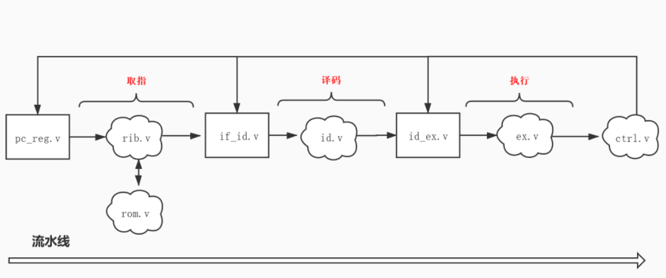
1. The rectangle represents the sequential logic circuit, and the cloud represents the combinational logic circuit. The process is as follows:
2. In the execution stage, when it is judged that a jump is required, send the jump signal and jump address to the ctrl(ctrl.v) module. After the CTRL module judges that the jump signal is valid, it will send it to the pc_reg,if_id and ID_ The ex module sends a pipeline pause signal, and also sends a signal to the PC_ The reg module sends a jump address.
3. When the rising edge of the clock comes, if_id and ID_ If the ex module detects that the pipeline pause signal is valid, it sends out NOP instructions, so that the whole pipeline (decoding stage and execution stage) flows NOP instructions, and the instructions that have been taken out will be invalid. This is the pipeline flushing mechanism.
In order to improve the efficiency of MCU. Therefore, different pipeline stages are suspended according to different pause signals. The specific operations are as follows:
/*
`define Hold_None 3'b000
`define Hold_Pc   3'b001
`define Hold_If   3'b010
`define Hold_Id   3'b011
*/
    always @ (*) begin
        jump_addr_o = jump_addr_i;
        jump_flag_o = jump_flag_i;
        // No pause by default
        hold_flag_o = `Hold_None;
        // Processing requests from different modules according to priority
        if (jump_flag_i == `JumpEnable || hold_flag_ex_i == `HoldEnable || hold_flag_clint_i == `HoldEnable) begin
            // For jump operation, pause from execution phase and pause from interrupt module, the whole pipeline is suspended.
            hold_flag_o = `Hold_Id;
        end else if (hold_flag_rib_i == `HoldEnable) begin
            // For bus pause, just pause the PC register to allow the decoding and execution phases to continue.
            hold_flag_o = `Hold_Pc;
        end else if (jtag_halt_flag_i == `HoldEnable) begin
            // For jtag module suspension, the whole pipeline is suspended.
            hold_flag_o = `Hold_Id;
        end else begin
            hold_flag_o = `Hold_None;
        end
    end
The bus pause is usually due to access to peripherals. Pausing the pc register is to extract the data required by the next instruction from the memory access operation of the current instruction; Only the pc register is suspended because the operation during accessing the peripheral does not conflict with the execution of the current instruction.
reference resources:
Write the blog of RISC-V processor | liangkangnan from scratch (gitee.io)